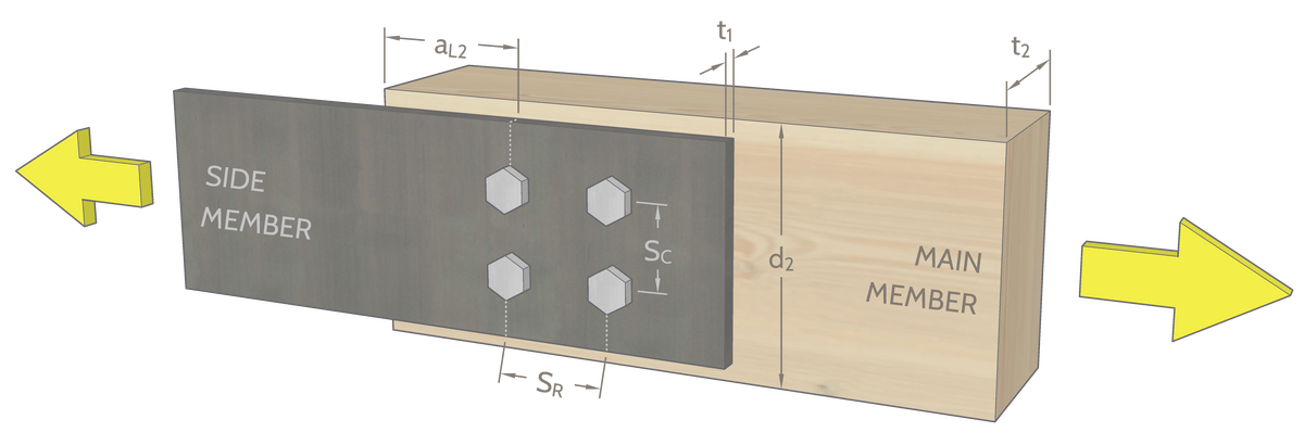
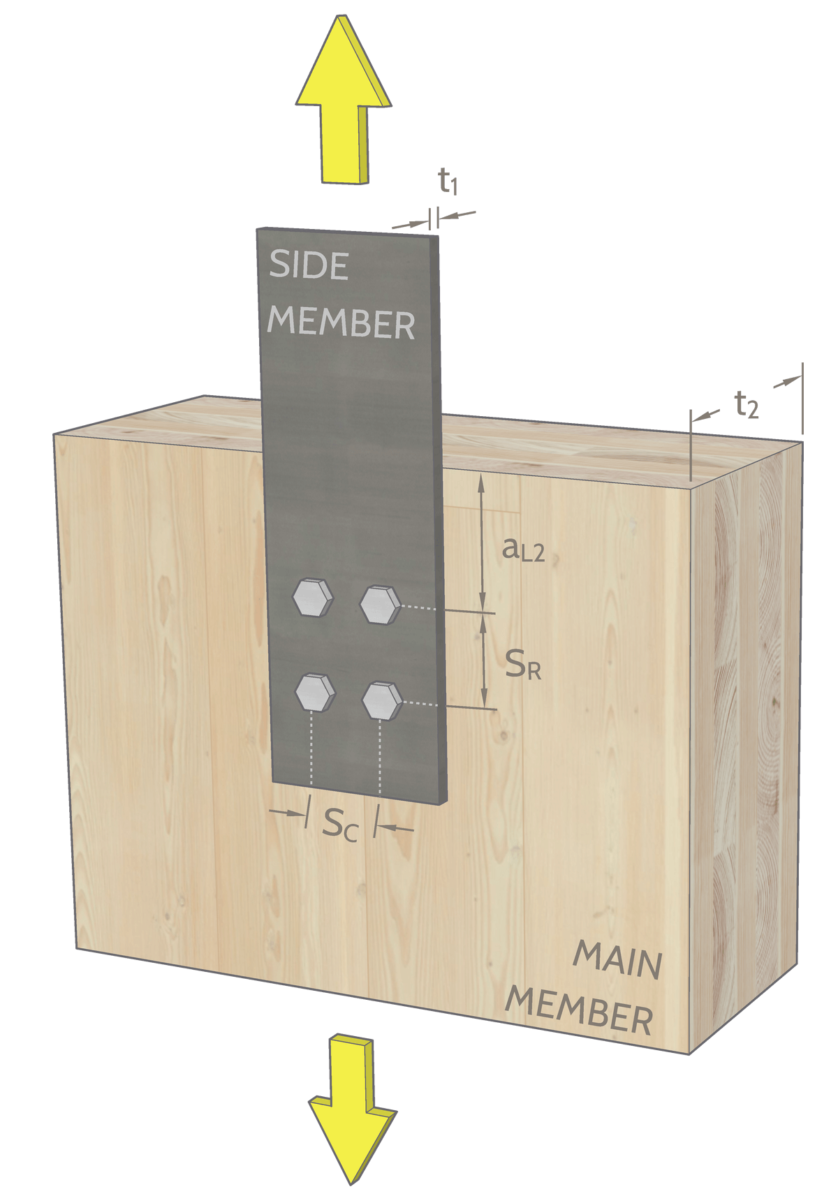
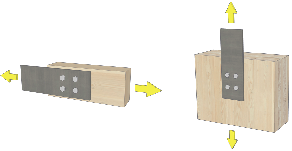
This interactive tool is intended for the design of Type 7 bolted connections based on CSA O86:24 Clause 12.4.
This tool is intended for use by builders/designers who are experienced and familiar with bolt design calculations.
KT is applied to the modes related to wood member resistance (Row Shear, Group Tear-Out, Net Tension), while KTC is applied to the yielding modes which represent the interaction between the bolt and wood member. See CSA O86:24 for treatment factor requirements.
Step 1 is all good! Move on to the next step.
The resistance of steel plate(s) needs to be checked separately.
Based on the selected dimensions, Member 1 uses a Light Framing grade.
Based on the selected dimensions, Member 1 uses a Beams and Stringers grade.
Based on the selected dimensions, Member 1 uses a Posts and Timbers grade.
Based on the selected dimensions, Member 2 uses a Light Framing grade.
Based on the selected dimensions, Member 2 uses a Beams and Stringers grade.
Based on the selected dimensions, Member 2 uses a Posts and Timbers grade.
The following dimensions are set as minimum, but you can change them as you see fit.
A parameter has changed. Please re-submit to update governing resistance.
An error occurred when generating the output. Please check your internet connection and try again.
We generated the result based on your selection.
Non-governing resistances and corresponding failure modes:
Non-governing resistances not found.