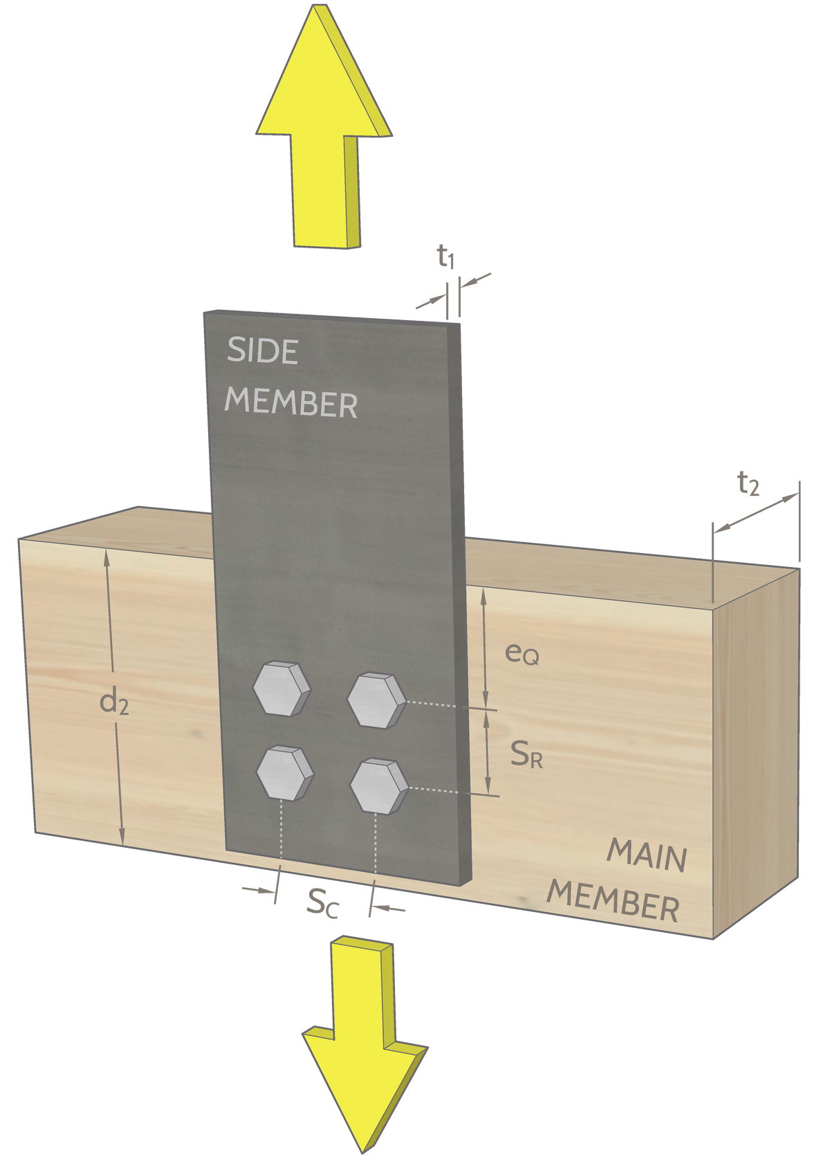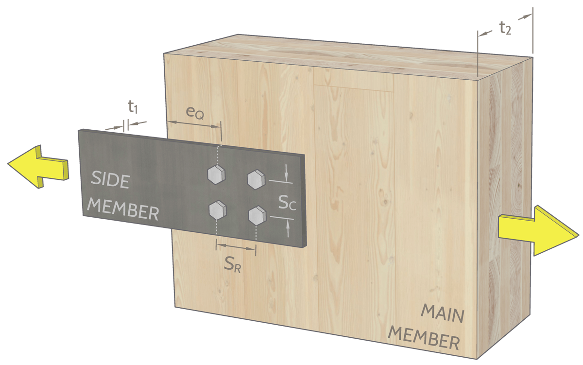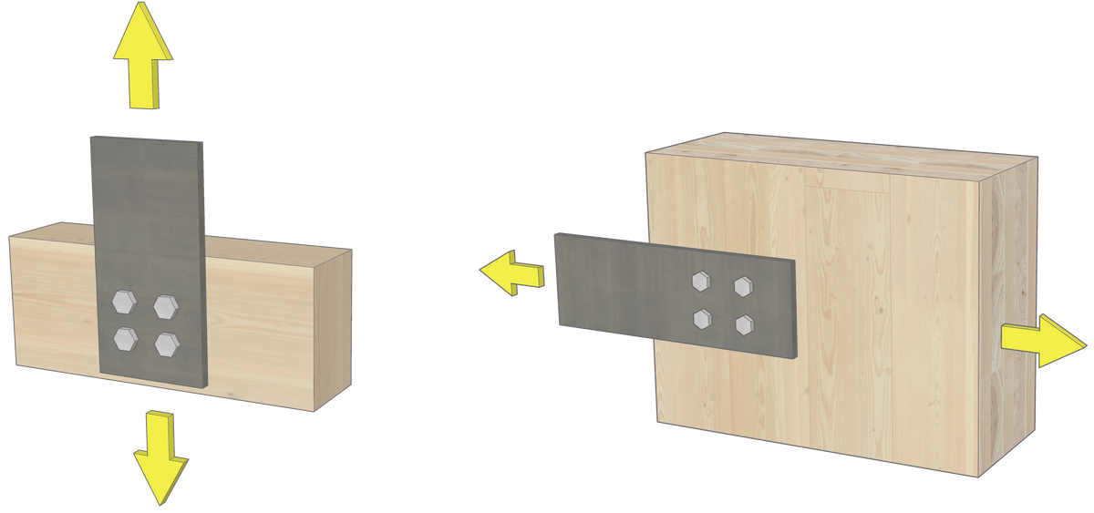

This interactive tool is intended for the design of Type 8 bolted connections based on CSA O86:24 Clause 12.4.
This tool is intended for use by builders/designers who are experienced and familiar with bolt design calculations.

KT is applied to the modes related to wood member resistance (Row Shear, Group Tear-Out, Net Tension), while KTC is applied to the yielding modes which represent the interaction between the bolt and wood member. See CSA O86:24 for treatment factor requirements.

Step 1 is all good! Move on to the next step.
The resistance of steel plate(s) needs to be checked separately.
Based on the selected dimensions, Member 1 uses a Light Framing grade.
Based on the selected dimensions, Member 1 uses a Beams and Stringers grade.
Based on the selected dimensions, Member 1 uses a Posts and Timbers grade.
Based on the selected dimensions, Member 2 uses a Light Framing grade.
Based on the selected dimensions, Member 2 uses a Beams and Stringers grade.
Based on the selected dimensions, Member 2 uses a Posts and Timbers grade.
The following dimensions are set as minimum, but you can change them as you see fit.
Main member shear resistance must be checked by the designer using effective depth, de =
A parameter has changed. Please re-submit to update governing resistance.
An error occurred when generating the output. Please check your internet connection and try again.
We generated the result based on your selection.
Non-governing resistances and corresponding failure modes:
Non-governing resistances not found.